MTA Tracker
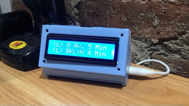
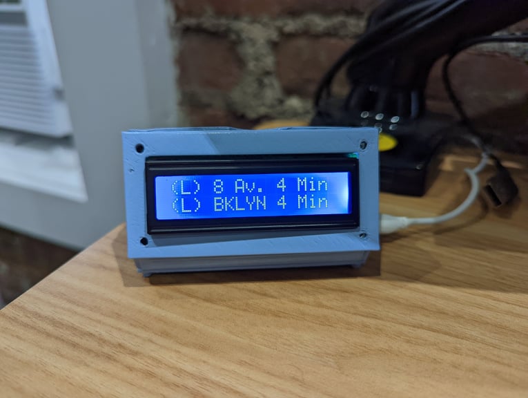
For a Christmas present (December 2022), I got to work assembling a small device that can take information from the New York MTA’s API, calculate how far the nearest few trains are from your desired station, and display this information, including train letter, direction, and arrival timing. My final device was based off Boscacci’s MTA-clock-esp32 tutorial on GitHub, with a few essential modifications in wiring & code.
Casing
While I could have designed my own case, Boscacci had already designed a neat, intuitive case, so I decided to use this for the final device. After 3D printing the parts, I sanded them down in layers starting with 180-grit sandpaper and ending at 550 or so to get a clean finish. Then, I spray painted the parts with blue paint which included primer and had a smoothened finish. This I did in 4 coats, waiting for 3-4 minutes in between each coat. I finally applied a clear, smooth finish after I let the paint cure overnight to finish the parts. The parts, which I had printed separately as flat pieces, were superglued together to make the final case.
Electronics
This was the trickiest part of the project. The core circuit was an ESP32, which I purchased from Amazon, and a rectangular 16x2 LCD screen compatible with Arduino electronics. When I bought my LCDs, the in-built contrast on the module was so low that it didn’t look like the LCD was working when I wired it. After much research, I discovered that I had to buy a 10kOhm potentiometer and attach that to one of the input pins. Here’s approximately how I wired the project:
Pin 1 LCD -> GND ESP32
Pin 2 LCD -> 5V ESP32
Pin 3 LCD -> Potentiometer data pin
Pin 4 LCD -> P14 ESP32
Pin 5 LCD -> P32 ESP32
Pin 6 LCD -> P26 ESP32
Pin 11 LCD -> P33 ESP32
Pin 12 LCD -> P27 ESP32
Pin 13 LCD -> P12 ESP32
Pin 14 LCD -> P13 ESP32
Pin 15 LCD -> 5V ESP32
Pin 16 LCD -> GND ESP32
Power input pin on potentiometer comes from 5V power supply pin on ESP32, goes to ground from ground pin. I had to solder a 4-way connection wire from the power pin to get the electronics to work.
These wirings are comparable to what you see with other tutorials. On the ESP32, you can use a bunch of different pin configurations; you just have to look up what pins are ok to use, and most ESP32s come with a guide on that. Make sure to adjust the pins in your code (check out the inbuilt liquidcrystal library in Arduino).
I started out with male-female crimps, and then soldered the wires directtly to the board for the best fit.
Code
Now for the code. I followed Boscacci’s instructions for how to set up a cloud server using AWS and was successfully able to create a server we could ping to and get MTA data. I modified the security to include all traffic from all IP vs. just my own. This step was easy to execute and access. We tested the server capability using Postman.
We used Arduino IDE to program the ESP32 module, following the initial steps from Boscacci. The main modifications we made to his code were to: (a) Use LiquidCrystal instead of the LadyAda LCD library. LadyAda kept on throwing odd errors for some reason. (b) Declare the LCD within the setup loop, as this is the only way to get the LCD to display (c) Change byte to int when we pull data from the server.
You can access the new Arduino code on my GitHub fork (https://github.com/anushamanglik/MTA-clock-esp32).
I used an old Amazon Kindle cable to upload data to the ESP32 & then plug the device into the wall.
Conclusion
And that’s it! It took a lot of time, exploration, and a bit of extra funds to make this project. Lots of fun and a rewarding output.